|
|
|
Make Position Array
This tool is used to make an NxM grid of an array of positions.
These are this tools options
|
The options include the Position Format String. |
The Positions by Count and Positions by Measure set, directly or indirectly, the number of positions.
The Positions By Count sets the number of NxM positions, where N is the Stride Count and M is the Extrude Count.
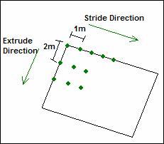
The Positions By Measure sets the stride direction, one position is set after Stride meters, and one position is set after Extrude meters.
For example: If Stride is 1, and Extrude is 2. The positions will be created in this way:

The Vectors Creation section has the same meaning shown in the tool Make Position Single.
After setting all of these options, go into a 2-D viewport (top, left or front) and create the rectangular region.
You set the first vertex of the region (the red one shown in the following figure) with the first click.
You set the second vertex of the region (the blue one shown in the following figure) with the second click. This sets the Stride Direction.
The last click, sets the Extrude Direction.
The following figures show the process:
|
|
*initial situation |
*after the 1st click |
|
|
*after the 2nd click |
*after the 3rd click |
copyright 2003 - Infinity Visions Inc. - all rights reserved
Created with the Personal Edition of HelpNDoc: Free Web Help generator